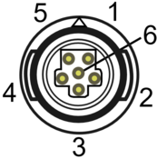
 Drawing of VBOX Sigma Top Connectors.
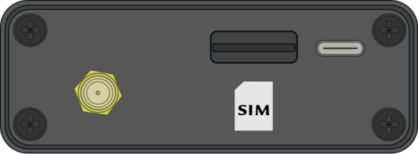
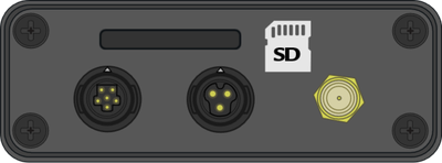
 Drawing of VBOX Sigma Bottom Connectors.
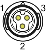
 Drawing of VBOX Sigma Top Connectors.
 Drawing of VBOX Sigma Bottom Connectors.
Connector 1 – 3G/4G Antenna
| PIN | I/O | Function |
|---|
| Centre | I | RF Signal/Power for active antenna |
| Chassis | I | Ground |
Connector 2 – SERIAL / CAN / POWER (Hirose 6 PIN)
| PIN | I/O | Function |
|---|
| 1 | I | RS232 Rx (Data in to VBOX Sigma) |
| 2 | O | RS232 Tx (Data out to VBOX Sigma) |
| 3 | - | Ground |
| 4 | O | CAN L |
| 5 | O | CAN H |
| 6 | I | V+ |
Connector 3 – POWER (Hirose 3 PIN)
| PIN | I/O | Function |
|---|
| 1 | I | Power |
| 2 | - | Ground |
| 3 | - | N/C |
Connector 4 – GNSS Antenna
| PIN | I/O | Function |
|---|
| Centre | I | RF Signal/Power for active antenna |
| Chassis | I | Ground |