MFD Touch Displays
This page contains an overview of the MFD Touch hardware. It will show the display unit and explain the connectors and LEDs.
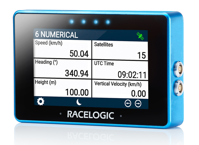
MFD Touch is a Multi-Function Touch Display designed to display GPS and CAN derived data channels from various VBOX loggers and sensors during testing.
It features an integrated touchscreen interface that is used to navigate and configure the data display screens, monitor the system readiness, control logging on the connected VBOX unit, and view live test data.
This page contains an overview of the MFD Touch hardware. It will show the display unit and explain the connectors and LEDs.
MFD Touch is a Multi-Function Touch Display designed to display GPS and CAN derived data channels from various VBOX loggers and sensors during testing.
It features an integrated touchscreen interface that is used to navigate and configure the data display screens, monitor the system readiness, control logging on the connected VBOX unit, and view live test data.

Connectors
Right Side of the Display
Refer to the Pinouts page for more detailed connector information.
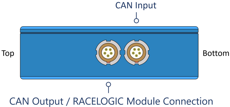
CAN Output/RACELOGIC Module Port
The top LEMO port on the MFD Touch provides CAN output.
This can be used to include the MFD Touch in a daisy chain with additional Racelogic modules connected to the VBOX system.
CAN Input Port
The bottom LEMO port on the MFD Touch is used to connect to the VBOX using the supplied RLCAB005-C cable.
CAN output is also available from this port when used with an RLVBACS024 CAN splitter.
The Left Side of the Unit
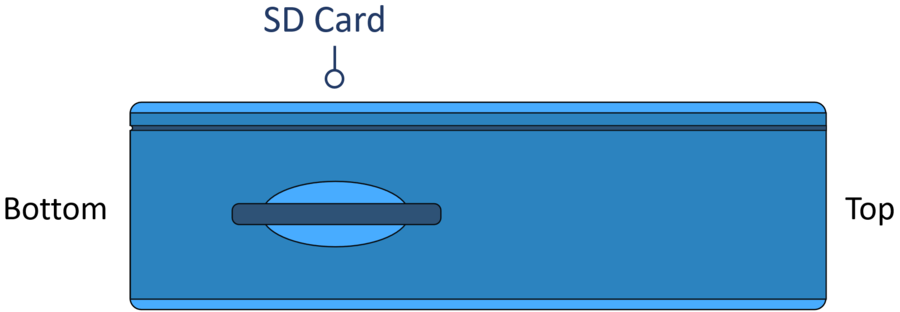
SD Card Slot
The SD card slot on the left side panel on the unit is used to insert the SD card MFD Touch uses to save and load settings, save test results and update the firmware.
LEDs
MFD Touch has 4 LEDs above the display. These LEDs are contextual feedback indicators tied to system state, user actions, and test behaviour, and they can flash in different colours and different patterns depending on the process the unit is performing.
Refer to the User Interface page for more details about the different LED behaviours.