Connectors
| Connector | Function |
|---|---|
| DATA 1 | Data 1 has Power, CAN, and Serial connections used to connect to VBOX data loggers or daisy chain with other modules. This port is also used for firmware upgrades. |
| DATA 2 | Data 2 has Power, CAN, and Serial connections used to connect to VBOX data loggers or daisy chain with other modules. |
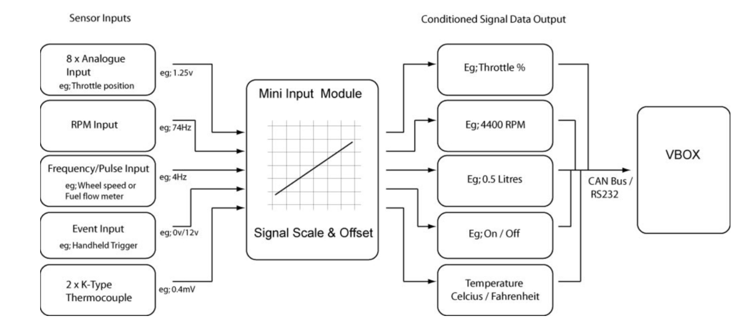
| TC1/TC2 | The MIM has 2 K-type thermocouple inputs. Each input is capable of measuring temperatures from 0 to 1000 °C. Each socket is the standard thermocouple socket format: See the Technical Specification for full thermocouple specifications. |
| AN1 - AN8 | All the analogue inputs are non-opto isolated 14-bit, 0 to 14 V inputs. They are all non-differential inputs that share the same ground. You can see the information about each separate pin on the Pinouts page. |
| AGND | The Ground pin for the analogue inputs. |
| +5V | Provides an isolated +5V output. |
| GND | Ground. |
| VPWR | A power supply that provides the same voltage as the current Input Voltage. |
| DOUT* | Frequency output of velocity (when connected to VBOX Mini). |
| AOUT* | Analogue output of velocity (when connected to VBOX Mini). |
| DIGIN1 | Digital Input 1. Optimised for event marking due to its internal 100 Kohm pull-up resistor, with a simple switch that connects the input pin to ground. The low state is below 4 V, so it can also be used as a TTL pulse input, such as fuel flow sensor inputs. |
| DIGIN2 | Digital Input 2. Optimised for a zero-crossing AC input signal, such as a Wheel speed signal or engine crankcase signal. |
| RPM** | Digital Input 3. Optimised for low-tension ignition coil signals. |
| GND | Ground. |
* The Analogue and Digital outputs are only available when connected to VBOX Mini, and the pulses/metre for the digital output and the max velocity for the analogue output can be configured in the Input Module menu on VBOX Mini.
- Press the MENU button on VBOX Mini and navigate to the Input Module menu.
- Use the arrow buttons to highlight the Setup Outputs option and press OK.
- Use the arrow buttons to navigate to the relevant setting and press OK to edit it.
- Use the arrow buttons to increase/decrease the value and press OK to confirm the new value.
** As many modern cars have their drive transistors included in the coil pack, you cannot connect to the low-tension connection on the ignition coil. However, you can access the 5V-switched RPM signal. In this case, as you are working with a switched signal of 5 V instead of the low-tension switched signal of 12 V from the coil, we recommend you use the DIGIN2 input instead of the RPM input.
Logged Trigger State
| Input State | Active - Low | Active - High |
|---|---|---|
| Low | High | Low |
| High | Low | High |
Example Connections
An example of how to connect an isolated individual potentiometer to the MIM.
Connecting to a potentiometer already installed on a car, such as a throttle potentiometer, would only require the output signal from the pot and the earth to be connected to the MIM as the pot gets its power from the car.


LEDs
| LED | Function |
|---|---|
| PWR | Indicates the power status of the MIM unit. |
| SC | Indicates the presence of serial signals on the DATA2 port. |
| TC1/TC2 | Indicates the connection status for Thermocouple connectors TC1 and TC2. |